

advantage over other solutions. Beside the cost-effective issue, the weight and profile are also
its strengths. Traditional ones are mostly controlled by hybrid tracking method, where the
antenna is steered electronically in elevation angle but mechanically in azimuthal plane. This
guarantees wide-angle scanning with small gain loss, but causes the problem of heavy weight
and high profile of the antennas. By LCD manufacturing process, it is possible to have light
weight and low profile of a 2-D steering phased-array antenna.
In the first part of this paper, different kinds of liquid crystal based phase shifters are
reviewed. The second part: A model calculating the linearity of such phase shifters is
demonstrated for the first time. The linearity is very important in the communication system
adopting carrier aggregation, and the issue is known as passive intermodulation, PIM. By
examining the performance of LC phase shifter and its linearity, the possibility to apply such
devices to terrestrial communication could be justified. The third part is to discuss the liquid
crystal based phased-array antenna which provides beam steering or polarization agility. The
fourth part is to brief the liquid crystal based metamaterial or metasurface antenna. This kind
of antenna provides the possibility of controlling not only the phase but also the amplitude at
the same time, which could be very useful when considering low side lobes. The reason why
the author chooses to discuss these two types of LC based antennas is the possibility of
commercialization. Certain progress has been made by separate start-up companies in recent
years with the help of LCD makers. This means in the near future one may see the
commercial product of these two kinds of LC based antennas. The last part is the material
development of liquid crystal for microwave applications. How to evaluate the liquid crystal
at microwave range is discussed.
2. Liquid crystal based phase shifters
Generally speaking, a passive phase shifter is evaluated by the figure of merit (FoM), the ratio
of the maximum phase shift (û-
max
) and the maximum insertion loss (IL
max
), given as follows
in (1). Obviously one would like the phase shifter to have larger FoM.
max
max
FoM
IL
∆Φ
= (1)
There are three major topologies of passive phase shifters. The first one is the switched-
line phase shifter with predefined paths of different electrical lengths and the switch realized
by P-I-N diodes, MOSFETs, or MEMS [1]. Since the paths have already been defined, there’s
no need for adjustable dielectric constant and thus liquid crystal is not suitable for this
topology. Besides, for a large antenna array the compactness and high phase-shift resolution
are required. The switched-line phase shifter is not appropriate for such application.
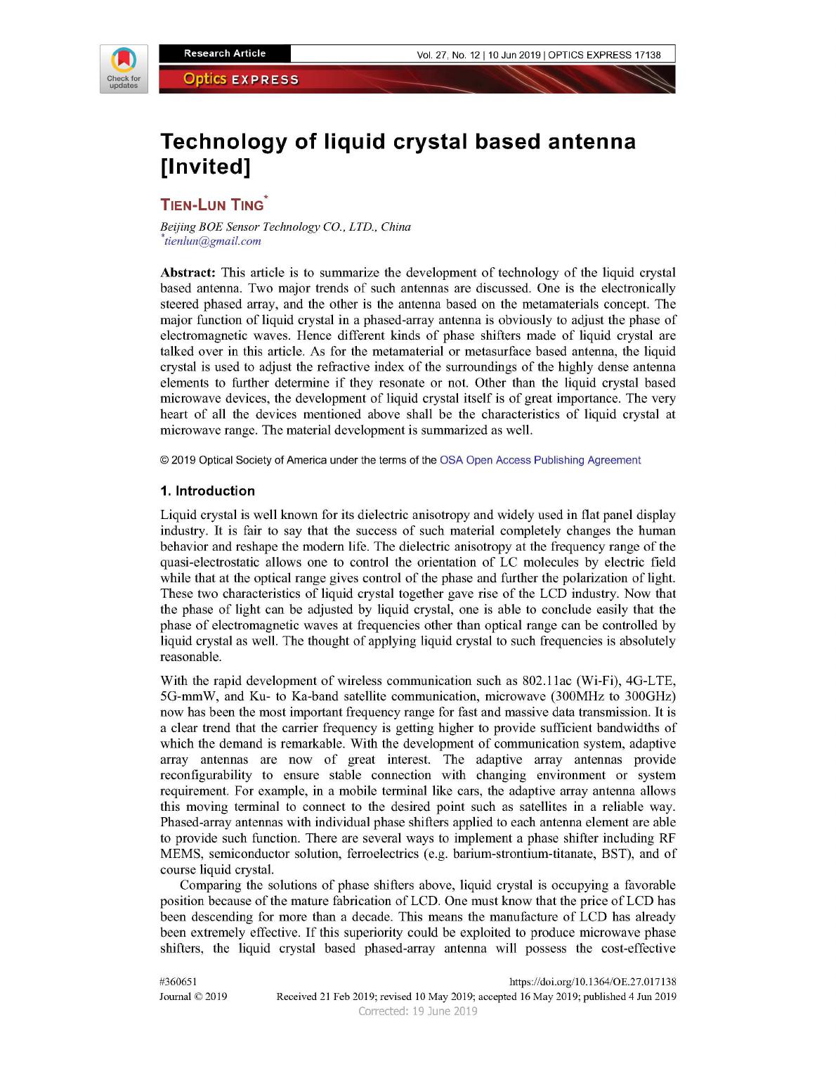
The second one is the reflection-type phase shifter (RTPS). This topology includes a
3dB/90° coupler and two tunable reflective loads which can be implemented by a varactor
diode [2]. There are, however, very limited studies about the liquid crystal based RTPS [3].
The schematic of the RTPS is shown in Fig. 1, where the variable capacitor can be realized by
liquid crystal. The reported FoM is only 12°/dB, which may not be the best performance of
the phase shifter of this type.
Vol. 27, No. 12 | 10 Jun 2019 | OPTICS EXPRESS 17139
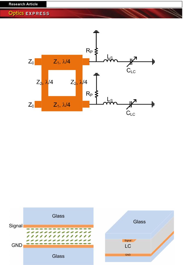
Fig. 1. Schematic of the RTPS with liquid-crystal varactors
The third type is the transmission lines loaded with shunt varators. There are basically two
structures of this type. The first one is the microstrip line (MSL) with bulk-like liquid crystal
as shown in Fig. 2. An MSL with bulk-like liquid crystal layer is formed [4–8]. Liquid crystal
is filled into the space between the signal and ground plane. By applying DC (or quasi-
electrostatic) voltage across the signal and ground electrode, the liquid crystal orientation is
altered. Since the mode of microwave propagating in an MSL is quasi-TEM, the electric field
is mostly perpendicular to the ground plane within the signal-electrode region, and thus the
shunt capacitance perceived by microwave will be determined by the liquid crystal
orientation. Owing to the nature of the microstrip line, the thickness of the liquid crystal layer
has to be larger than 100um when considering propagation loss [4]. This causes a problem of
extremely slow response of liquid crystal, which could take several seconds to switch from
one state to another. If the phased array requires fast response, the structure will not be
suitable. Among these researches, the highest FoM that has been reported is 110°/dB [6]
because of properly designed liquid crystal for microwave range.
Fig. 2. Schematic of loaded transmission line
Figure 3 demonstrates the other structure of the loaded transmission line. It is the coplanar
waveguide (CPW) periodically loaded by shunt liquid-crystal varactors [9,10]. Because the
periodic capacitance has relatively short electric length comparing to the wavelength, it can
be regarded as the lumped-circuit element. The amount of shift of phase of one period will be
determined by the ratio of each periodically loaded capacitance to the shunt capacitance of the
original transmission line in one period. Due to the nature of a periodic structure, this kind of
phase shifters always has a Bloch frequency at which strong reflection occurs. To avoid poor
S
11
, it is necessary to make Bloch frequency much higher than the operation frequency. The
Vol. 27, No. 12 | 10 Jun 2019 | OPTICS EXPRESS 17140
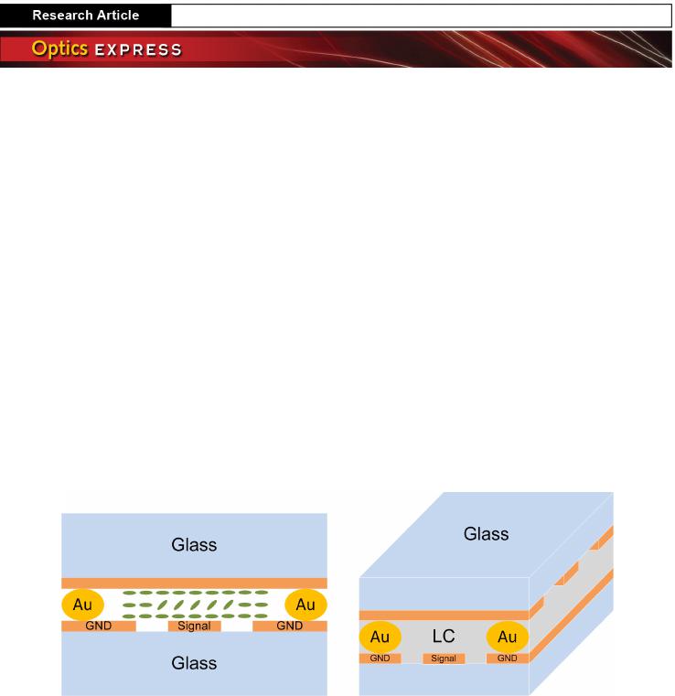
voltage controlling liquid crystal should be applied across the signal and ground electrode in
Fig. 3. Au balls are implemented to connect the GND on the bottom substrate to those on the
top substrate. This is a very common process in standard LCD fabrication. The gold balls
have diameters slightly larger than the designed cell gap to guarantee the connection between
GND electrodes. The cell gap (less than 10um) is much smaller than the spacing between
signal and ground electrodes (could be several hundred microns, depending on the impedance
of CPW) on bottom substrate. Only the liquid crystal sandwitched by signal and top GND
electrodes will be reoriented by the DC (or quasi-electrostatic) voltage. The major benefit of
this structure is that the thickness of the liquid crystal layer can be lowered to several
micrometers, which is almost the same as the cell gap of an LCD. This brings two advantages
over the previous LC-bulk MSL. One is the response time restored to milliseconds, and the
other is the compatibility of LCD manufacturing process. The former one is certainly
important and easy to understand, and yet the latter one matters as well. Since the modern
liquid crystal filling process (ODF) of an LCD mass-production line is specifically designed
to produce LC cells with several microns, it is difficult for current equipment to manufacture
devices with cell gap larger than 100um. From the viewpoint of mass production, designing a
liquid crystal based phase shifter with cell gap less than 10um is very helpful. According to
author’s experience, this structure could give similar FOM performance as that in Fig. 2.
Fig. 3. Schematic of periodically loaded transmission line
Besides the above topologies, there are several other types of phase shifters made with
liquid crystal [11–15] including CPW with liquid crystal filled into space between coplanar
ground and signal electrodes [12,15], a CMOS slow-wave CPW incorporated with liquid
crystal [11], a ring-resonator [13] and a bandpass filter [14] whose passband and phase can be
tuned by liquid crystal at the same time. These types of LC phase shifters are however not as
compatible to current LCD manufacturing process as the three types mentioned above. Hence,
the author chooses not to discuss them in details.
3. Liquid crystal based phase shifters
Whatever the topology is, one usually aims to increase the FoM and shrink the size of the
phase shifter so as to apply this technology to the phased-array antennas. However, these two
factors are not only requirements. For example, the base stations of a cellular network may
use phase shifters to adjust the elevation of the phased array to have different coverage when
it’s necessary. With the popularity of 4G-LTE, mulitcarrier is introduced to exploit ultra-wide
bandwidth, which is called carrier aggregation. The base-station antenna radiates multiple
carriers with different frequencies simultaneously. This makes the linearity of the whole
communication system a very important issue. For a passive microwave component like a
liquid crystal based phase shifter, to evaluate its linearity is to measure its PIM. To study this
phenomenon in a liquid crystal based phase shifter means to figure out the third-order term of
susceptibility, $
(3)
, of liquid crystal at the frequency range of microwave. Lots of researches
about the nonlinearities of liquid crystal at the optical range have been made [16,17] but few
at the microwave range [18]. The IP3 in [18] of a LC phase shifter looks quite promising, and
Vol. 27, No. 12 | 10 Jun 2019 | OPTICS EXPRESS 17141
the reason is
p
aper a sim
u
with periodic
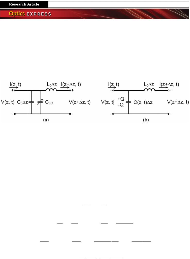
The C
LC
is
t
capacitance
o
liquid crystal
,
will be consi
d
shown in Fig.
Fig.
4
positi
o
To descri
b
equations ca
n
voltage of tr
a
right hand s
i
capacitances.
nonlinear me
d
medium and
a
is the nonli
n
Comparing (
4
that of (5).
To use (4
)
how capacita
n
describe the
d
b
e homogen
e
director tilt a
n
elastic const
a
frequencies.
E
derived fro
m
capacitance
v
molecular re
o
capacitance v
that the LC
m
lation model
t
a
lly loaded L
C
t
he shunt var
a
o
f transmissio
n
,
C
LC
may cha
n
d
ered as a fun
c
4(b).
4
. Equivalent circ
u
o
n dependent cap
a
b
e the wave
t
n
be re-written
a
nsmission lin
e
i
de of (4) ac
c
This is very
d
ium as given
b
a
ccounts for t
h
n
ear
t
erms of
4
) to (5), one
c
2
0
2
V
L
z
∂
−
∂
)
to predict th
e
n
ce changes
w
d
ynamics of L
C
e
ously aligned
n
gle with res
p
a
nts, respectiv
e
E
is of cours
e
m
(7), the LC
v
ariation can
b
o
rientation, a
n
ariation as de
m
m
olecules are
m
t
o describe su
C
capacitance
c
a
ctor to adjus
n
line to form
n
ge with the
v
c
tion of time
a
u
it of transmission
a
citance
t
ravelling wit
h
as (2) and (3
)
e
. Comparing
t
c
ount for the
n
similar to the
b
y (5), where
E
h
e linear part o
f
the medium
i
c
ould interpret
∂
I
Q
z t
∂ ∂
= − =
−
∂ ∂
( )
2
0
2
,
V
C z t
t
∂
=
∂
2
2
2
n
c
∇ −E
e
PIM perfor
m
w
ith time and
p
C
directors rea
c
. In (6), x-dir
e
p
ect to the ho
m
e
ly. û0 is the
d
e
the electric
states evolvi
n
b
e calculated.
n
d the results
m
onstrated in
F
m
uch slower i
n
ch phenomen
o
c
an be equiva
l
t phase, and
a total capaci
t
v
oltage across
i
a
nd position t
o
line (a) with shu
n
h
equivalent c
)
. They lead t
o
t
o the original
n
onlinear effe
equation of
e
E
is the electri
f
the medium;
c
i
ncluding all
the right han
d
0
V I
L
z t
∂
∂
=
∂
∂
( )
,
V
C z t
V
t
∂
−
−
∂
( )
0
,
2
C z t
L
t
∂
∂
∂
∂
2
2
2 2
0
1
t c
ε
∂ ∂
=
∂
E
m
ance of an L
C
p
osition. The
E
c
ting to applie
d
e
ction is alon
g
m
ogenous alig
n
d
ielectric anis
o
field of micr
o
n
g with micr
o
This method
show that o
n
F
ig. 5. The pul
s
n
their reactio
n
o
n is develop
e
l
ent as the cir
c
one can com
b
t
ance. Becaus
e
i
tself. Therefo
r
o
reflect the fa
c
n
t LC varicap and
c
ircuit of Fig.
o
Eq. (4) whic
h
equation, the
e
ct caused by
e
lectric field
o
i
c field; n is th
e
c is speed of l
i
the orders o
f
d
side of (4) a
s
( )
,C z t
V
t
∂
∂
(
2
0
C
V
L V
t t
∂
∂
+
∂
∂
2 NL
2
t∂
P
C
based phase
E
ricksen-Lesli
e
d
electric fiel
d
g
cell gap, a
n
n
ment. K
1
and
o
tropy of liqu
i
o
wave. By as
s
o
wave electri
c
gives nonlin
e
n
ly longer mi
c
s
es in Fig. 5(a
)
n
to the RF be
a
e
d. A transmi
s
c
uit shown in
m
bine it to th
e
e
of the nonli
n
r
e, the total ca
p
c
t of wave tra
v
d
(b) with time an
d
4(b), the tele
h
gives the b
e
extra two ter
m
the voltage
d
o
f wave prop
a
e
refractive in
d
i
ght in vacuu
m
f
electric susc
e
s
the nonlinea
r
(
)
2
,z t
shifter, one
m
e
Eq. (6) can
b
d
. The cell is a
s
n
d represent
d
K
3
are splay
i
d crystal at
m
s
igning LC in
i
c
field and f
u
e
arity of the
c
c
rowave pulse
)
and 5(b) are
s
a
t. In this
s
sion line
Fig. 4(a).
e
original
n
earity of
p
acitance
v
elling as
d
grapher’s
e
havior of
m
s on the
d
ependent
a
gation in
d
ex of the
m
, and P
NL
e
ptibility.
r
terms as
(2)
(3)
(4)
(5)
m
ust know
b
e used to
s
sumed to
s the LC
and bend
m
icrowave
i
tial state
u
rther the
c
ollective
s lead to
s
ignals of
Vol. 27, No. 12 | 10 Jun 2019 | OPTICS EXPRESS 17142